ClodPi Labs - LoRaWAN Gateway - Outdoor - Getting Started
The Gateway (Outdoor) opens up an abundance of opportunities, allowing the ability to mount the Gateway onto the side / top of buildings, houses, terrace / roofs - an ideal solution for wider coverage applications across villages, towns and cities.
The document describes the characteristics of Gateway (Outdoor) and gives a reference of how to install the same.
Prerequisite:
User should be ready with these basic things before hand:
- Uninterrupted power supply
- Uninterrupted internet connection
- An identified place where Line of Sight is clear for better Coverage.
- Avoid locations - like basements, closed rooms, inside cabinets, where strength of the signal can become weak.
- A smart mobile phone / Laptop with internet connection.
- Users need to purchase following items separately:
a) One micro SIM (4G)
b) RJ45 Ethernet (cat5e or cat6) Shielded Twisted Pair (STP) cable in order to connect your internet router with your Gateway outdoor setup. The length of the cable will depend on the distance between your PoE Inject / internet router and the outdoor enclosure where it is being deployed (Terrace / roof / any other location).
Note:
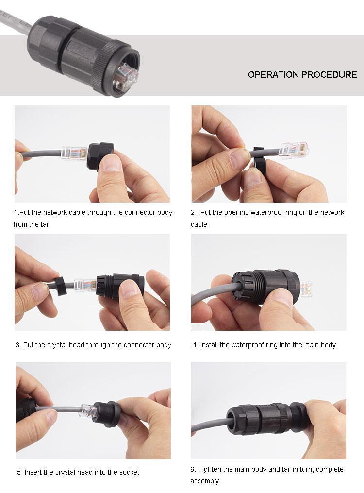
(i) Follow T568B standard for crimping. Avoid the T568A standard.
(ii) Refer to the ‘Operation Procedure’ for connecting the RJ45 ethernet cable through the RJ45 connector.
Refer to the ‘Operation Procedure’ for connecting the RJ45 ethernet cable through the RJ45 connector.
c) Ethernet cable with crimps to connect the PoE Injector and Internet Router.
d) Two Earthing / Copper wire in order to connect surge-arrester with the earthing / grounding mechanism to protect the Gateway from a lightning strike.
e) Mounting Flagpole of non-rusting material having diameter between 2 inches. Length of the flagpole is your choice to get a clear line of sight for your Gateway. Note: Height of flagpole should be enough so at to avoid any person easily reaching the gateway and allow tampering with the set up.
f) Clamps and anchor bolts to securely install the mounting flagpole on your terrace, roof or any other identified location.**
g) Identify a location on your terrace/roof and fix the Flagpole using Clamps and anchor bolts in such a way that the tip of the pole and base of the antenna has no obstructions like concrete walls, brick walls, metal mesh, metal grills, trees, magnetic materials.
Note: Avoid locations with possibility of water stagnation, ants’ infestation, etc.
h) Screwdriver (PH1, PH2) with ability to screw slotted and cross head (Philips) screws.
i) Flat nose plier for fixing the earthing wire.
j) Wrench for tightening the Hose Clamps.
k) 8 mm spanner for U-bolt and 18 mm spanner for tightening Antenna to L-Clamp.
|
|
Package Content:
|
ClodPi’s Gateway (Outdoor) device package comes with the following items:
| SN |
ITEM |
QUANTITY |
| 1 |
ClodPi’s Gateway (Outdoor) (IP67, ASA material) |
One |
| 2 |
Breathers |
Two |
| 3 |
RJ45 Connector (Grade IP67) |
One |
| 4 |
N - Female connector |
One |
| 5 |
LoRa Antenna (3.5 dbi, N-Female, Fiberglass) |
One |
| 6 |
Surge Arrester (for earthing) |
One |
| 7 |
Antenna Cable (N-Male to N-Male) |
One |
| 8 |
Cable Lug (for earthing) |
One |
| 9 |
PoE Injector 802.3at (48V, industry grade) with power cord |
One |
| 10 |
Gateway mounting Plate |
One |
| 11 |
Gateway Mounting Metal Hose Clamps |
Two |
| 12 |
Antenna Mounting Metal Bracket Kit (suitable for 2 inch Flagpole) |
One |
| 13 |
Waterproof Tape |
One |
| 14 |
Insulation Tape |
One |
| 15 |
M4 Screws (for mounting plate) |
Four |
|
Safety Instructions:
|
Users are requested to strictly follow the important points mentioned below while setting up the Gateway (Outdoor) device and and strictly follow the user guide and safety instructions to avail the Warranty:
- IMPORTANT: Do not power on the Gateway without the LoRa antenna connected as this may damage the gateway.
- Even though the Outdoor version is designed to be used outdoors in all weather conditions, it is highly recommended to safeguard it from all the factors of harsh environments and keep away from electrical appliances with strong magnetic / electric fields.
- Do not try the set up in underwater / submerged mode or near to Fire.
- All the connectors on the outdoor enclosure are already tightened to the maximum possible. Users are requested to maintain the same.
- The setup is expected to work under direct sunlight / rain but if possible do provide some shade (non-metal) to the enclosure box. Noon time of the day is when the Sun is at its peak temperature.
- In open to sky mode, there is always a risk of lightning strike during monsoon season which may damage the device. For protection from lightning, it is important to use surge resistor / protection between the outdoor enclosure box and the antenna to avoid any untoward damage to your Gateway device in the event of a lightning strike or similar incident.
- Do not attempt to open the enclosure. Non-expert handling of the device could damage it. Consult the manufacturer for help, or else it may cause short-circuit, fire, electric shock or breakdown.
- Avoid wetting the inner side of the enclosure with any liquid / fluid.
- Use of any third-party accessories [outdoor enclosure, power supply, custom antenna, splitters, amplifiers] other than the stock items provided by default with the device by ClodPi Labs will be at the user’s discretion.
- Do not install, use or service the device during a thunderstorm. Please keep the cable disconnected.
- It is advisable to first complete the configuration process for ClodPi’s Gateway (Outdoor) as mentioned before installing the same in outdoor locations.
- Be ready with the materials as mentioned in the “Prerequisite” section above.
|
Gateway Enclosure - Introduction:
Note: The images shown are for depiction purposes – actual color may slightly vary.
|
Steps to set-up the device:
|
Open the ClodPi Labs Gateway (Outdoor) package and take out all the items. Once the Gateway configuration process is complete then we will install the device at the selected outdoor location.
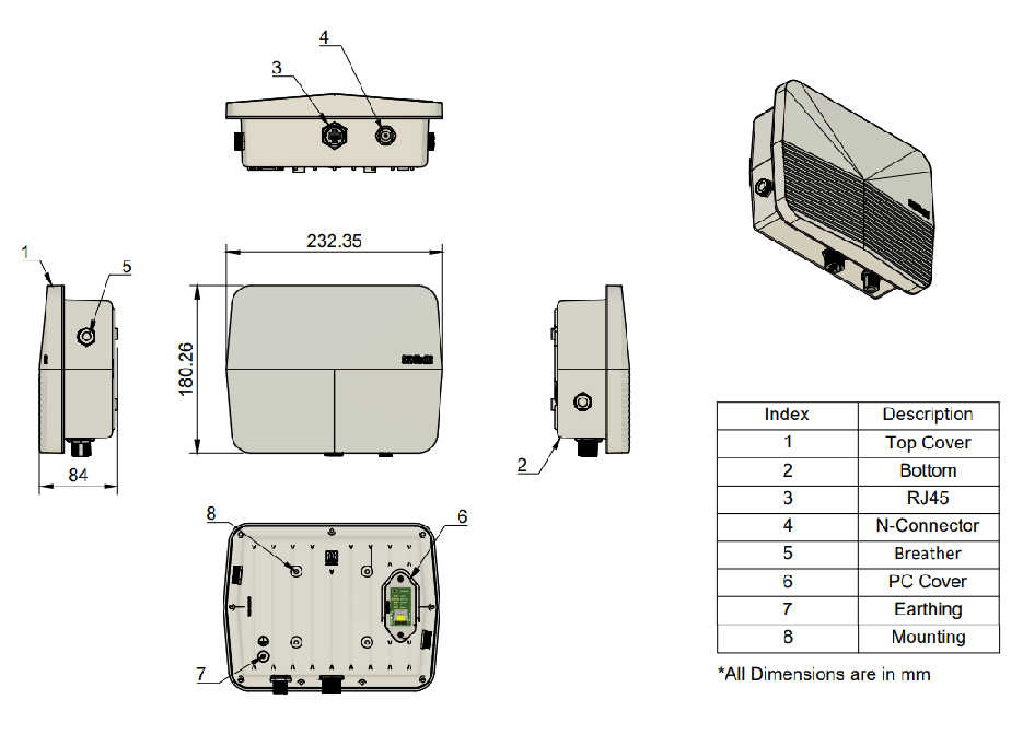
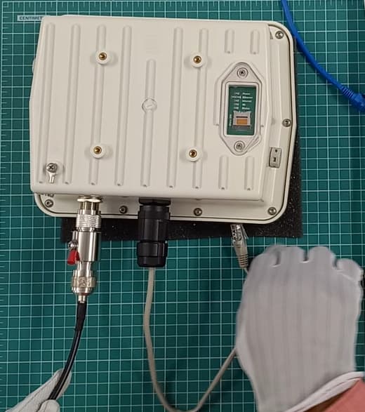
Step 1. Gateway enclosure: Take the enclosure and make sure on the following:
- Antenna connector: One
- RJ45 connector: One
- Breather: Two
- Lug cable: One
- Device ID sticker: Make note of the device details for future reference
- PC Cover (transparent) at the back side
|
|
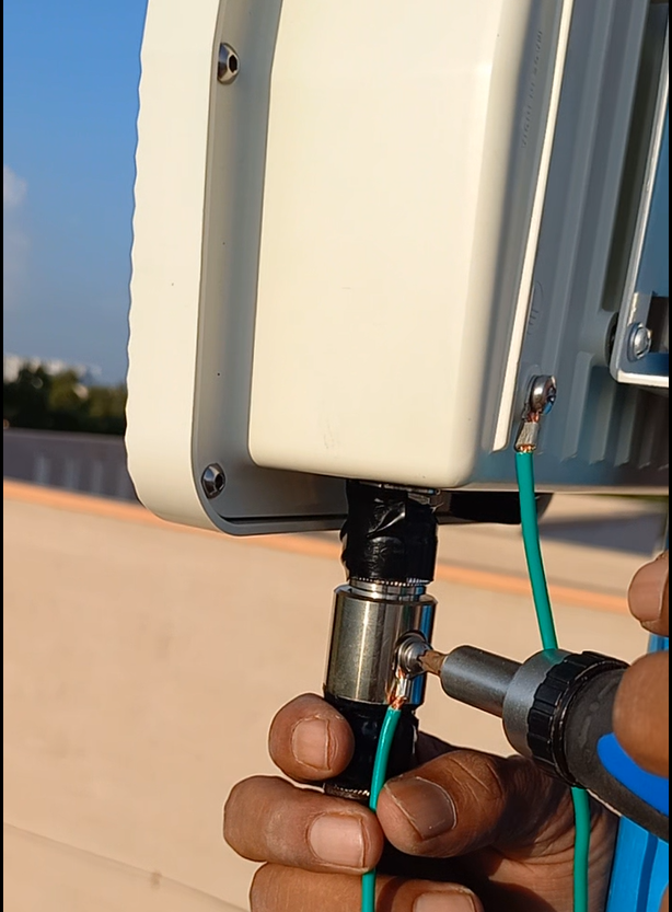
Step 2. N to N cable:
- Take the N to N cable and connect one end to the Surge Arrester. Tighten it appropriately.
|
|
- Take the antenna, remove the nut and washer. Take the the other end of N-N cable and connect to the antenna as shown in the image.
Note: We must safeguard the antenna to cable connection, cable to surge-arrester and surge-arrester to enclosure joints for any water slippage by using the Water-proof tape and Insulation tape. The same is explained in later steps.
|
|
|
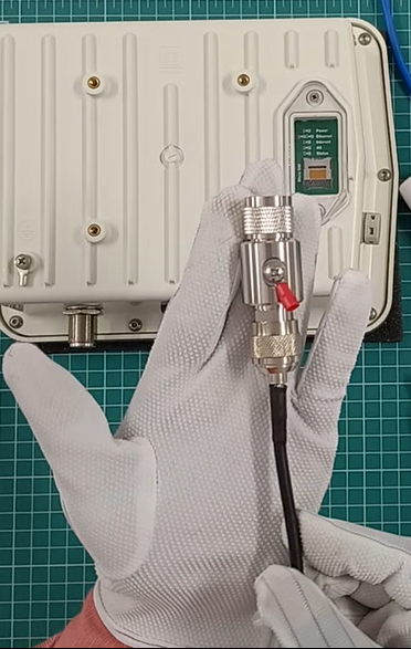
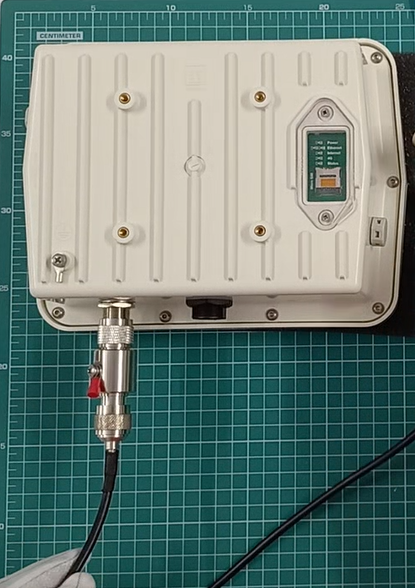
Step 3. Surge arrester: Take the surge arrestor and connect it to the N-Female connector at the enclosure as shown in the image.
|
|
|
Step 4. Now take the other end of RJ45 Ethernet (cat5e or cat6) cable and connect to the RJ45 connector at the outdoor enclosure.
Note: Refer “Operations procedure” steps at the “Prerequisite” section to understand how to set-up the RJ45 connector over the RJ45 Ethernet cable.
|
|
|
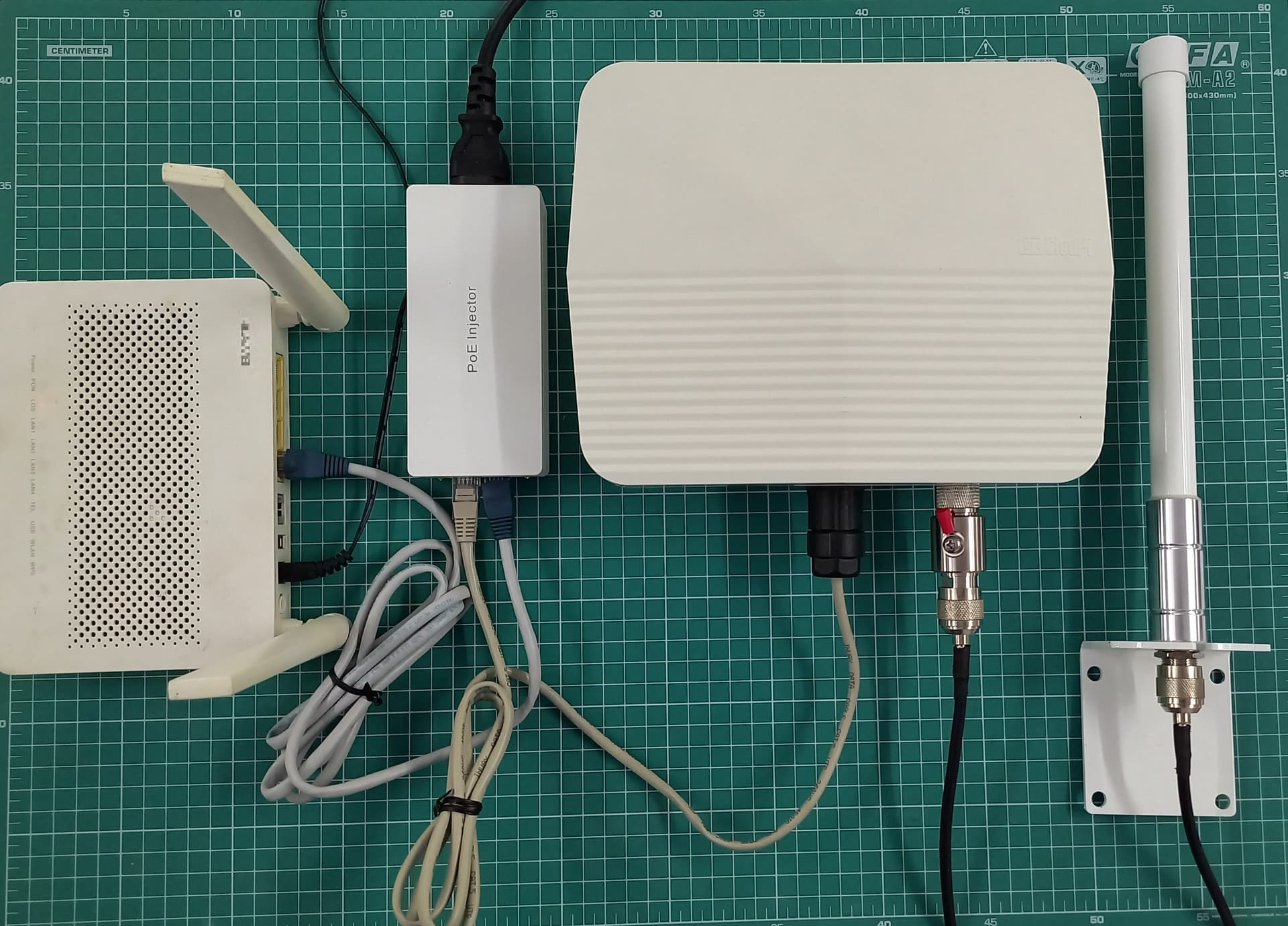
Step 5. Power: To provide power to the gateway, we will be using Power over Ethernet Injector (PoE - IEEE 802.3at) provided along with the package by connecting the PoE Injector with the power mains and to the gateway:
- Connect the POE Injector power cord (black) to the PoE Injector.
- Take the RJ45 cable (cat 5 or cat6) and connect its one end to Data & PWR Out jack at PoE Injector and the other end to the Device.
- Take the Ethernet cable with crimps and connect one end to the PoE Injector and other end to the Internet Router.
- DO NOT switch ON the mains unless RJ45 cable (cat 5 or cat6) is connected to the device.
- Connect the power cord of the PoE Injector with the power main. The complete setup should be like the adjacent image.
Note: This image is a depiction. In a real situation, the enclosure will be at the location where you want to mount it. PoE Injector will be near the power main.
|
|
|
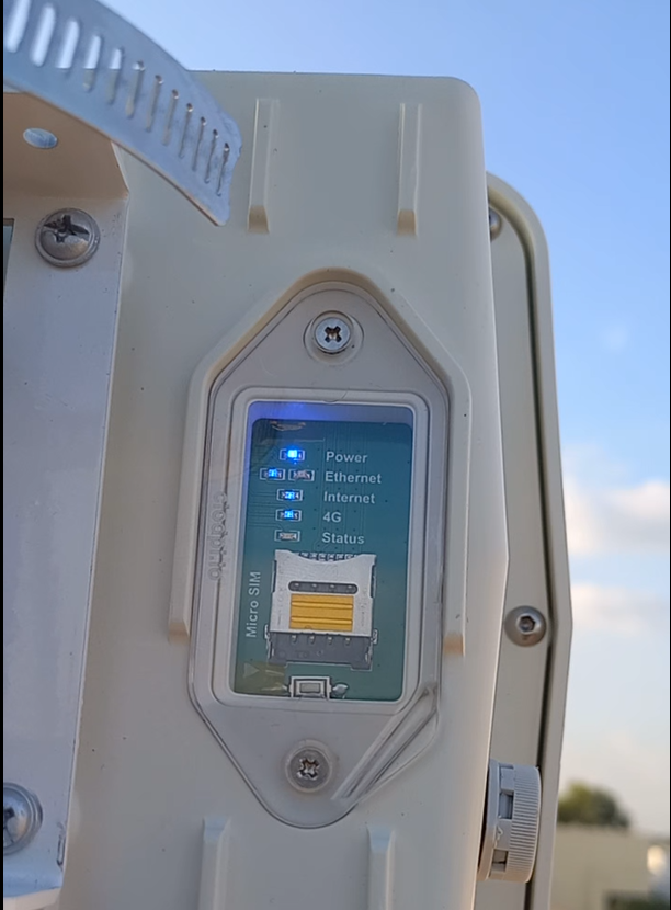
Step 6. Switch on the power for POE Injector. Observe the Power LED on the back side of the Gateway enclosure.
| LED Indicator |
DESCRIPTION |
| Power |
The LED is lit when the power supply is ON. |
| Ethernet |
The LED will lit when the internet supply is ON. |
| 4G |
The 4G LED will not lit as instead of SIM Card, ethernet cable is used. |
| Internet |
The Internet LED takes 3 to 4 minutes to lit after the Ethernet LED is lit. |
| Status |
LED will be lit when Gateway is successfully configured. |
|
|
|
Step 7. Power ON LED should be lit immediately when Power is switched ON. This will start the first booting of the device.
Step 8. Ethernet LED will lit within few seconds.
Step 9. 4G LED will not lit in Gateway without 4G option.
Step 10. The Internet LED is lit after 3 to 4 minutes. This ensures internet data supply.
Step 11. When the first boot process is complete, the Internet LED should also be lit. This may take a few minutes. Once the internet LED is lit, the device is ready to be configured.
Note: Status LED will be lit when the Gateway up and running.
|
Install the Gateway in an open to sky location
- Switch Off the mains
- Remove the RJ45 connector (Cat5e or Cat6 internet cable)
- Remove N to N cable from Surge Arrester connection
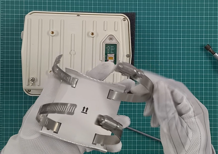
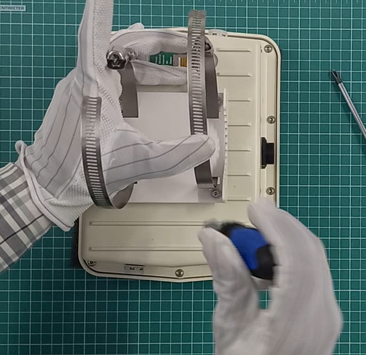
Step 12. On base of the outdoor enclosure, fix the bracket and hose clamps using the screws provided along with the outdoor accessories:
- Take the enclosure and keep upside down
- Take the bracket.
- Take both the metal hose clamps and open them up.
- Insert both the metal hose clamps as shown into the hole provided in the bracket.
- Now place the bracket with metal hose clamp on to the back side of outdoor enclosure bottom
- Make sure to align the bracket on to the bottom as per the arrow marks (This side up) provided
- Using the four M4 screws, tighten the bracket on to the enclosure bottom on all the four corners. You might need to press / bend the Hose clamp a bit to be able to place the screws on to the screw-hole of the metal bracket.
|
|
|
Step 13. Take the following items to the identified location of installation:
- Gateway Enclosure
- LoRa Antenna
- LoRa Antenna mounting clamp setup (L-Clamp, U-bolts)
- N to N cable
- One end of Cat5e or Cat6 cable.
*Other end will be connected to the PoE Injector near the power mains.
- Enclosure Mounting kit (Metal Bracket, M4 screws, Metal Hose clamps)
- Earthing cables
- Weather proof tapes
- Tools like Screwdriver, Wrench, Flat nose plier.
|
|
Step 14. First install the flagpole on the location.
|
|
|
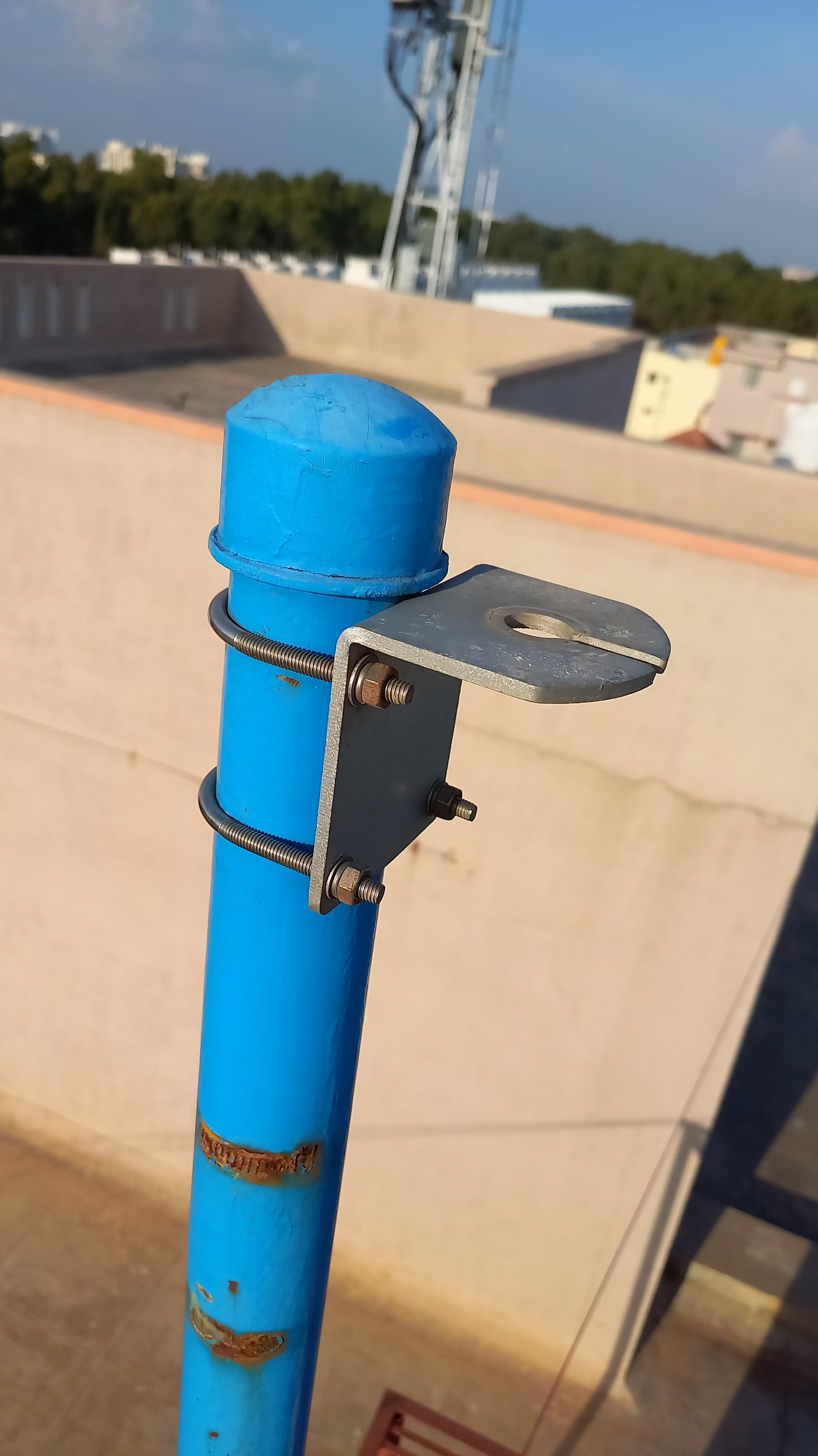
Step 15. Mount Antenna on the Flagpole:
- Take L - clamp and fix it on the flag pole using the U bolts near to the top / tip of the flagpole such that it is little above the Gateway enclosure.
- Take the N to N Cable
- Connect one end of N to N cable to the surge arrestor.
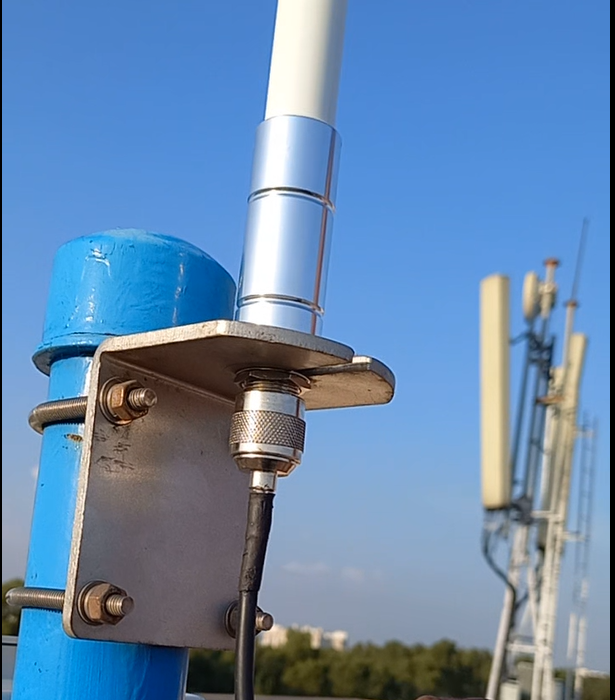
- Take the antenna and remove the nut and the washer.
- Place the antenna on the aperture available on the mounting L-clamp.
- Tighten the washer and nut so that the antenna is securely fitted on to the L-clamp
- Connect one end of the N to N cable to the antenna and tighten it properly.
|
|
|
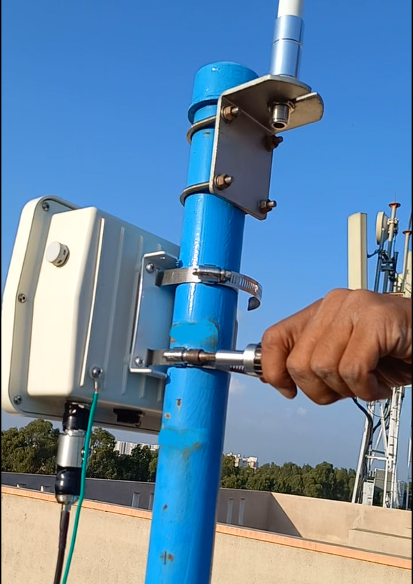
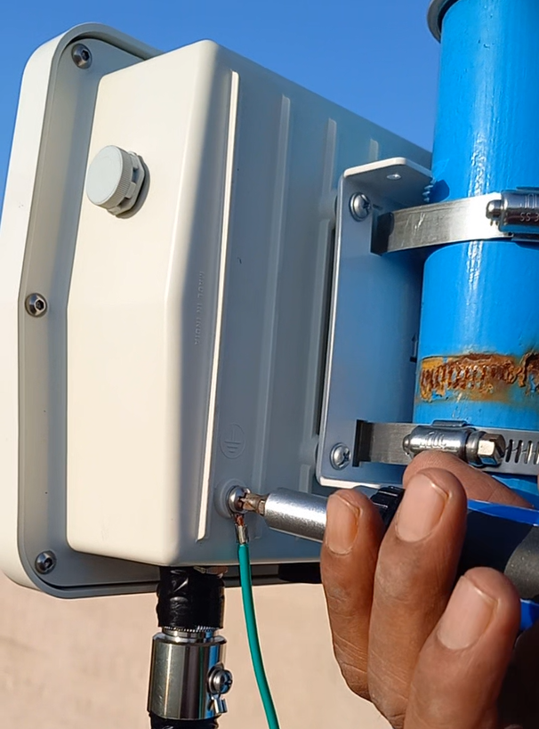
Step 16. Mount the Gateway Enclosure on the flagpole:
- Hold the Enclosure and keep the bracket teeth on to the side of the flagpole at a height from which the N to N cable easily reaches to the Antenna and the Surge Arrester which is fitted on to the bottom of the enclosure. Also the height should be easily accessible to be able to remove the Enclosure from the flagpole in case of any need.
!!!Caution!!!
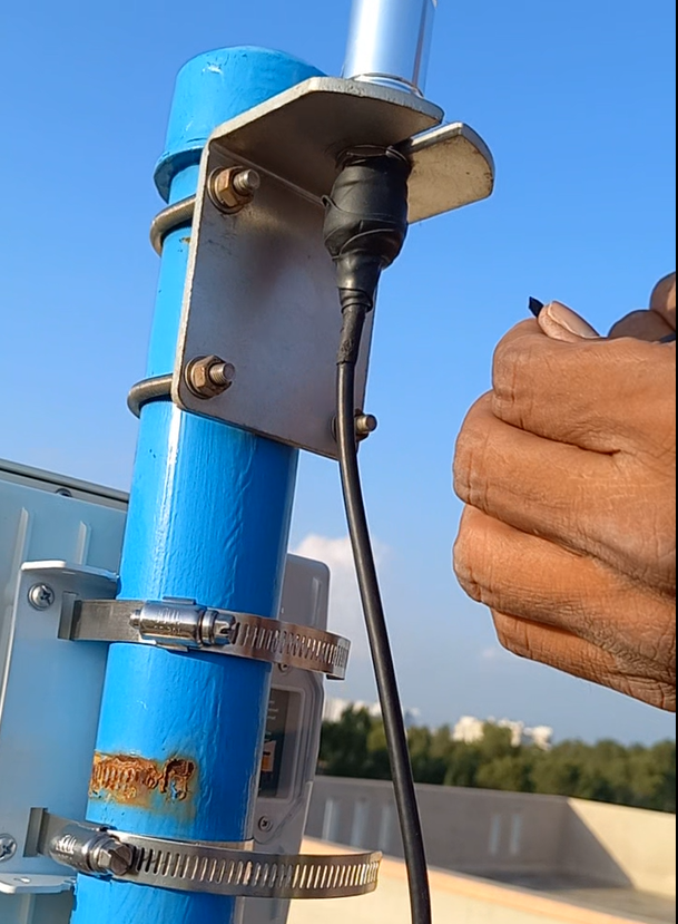
- The Gateway enclosure should always be mounted in a way where the RJ45 connector and Antenna Connector on the enclosure are facing downwards as shown in the adjacent image.
-
Do not mount the enclosure in a way that RJ45 connector and Antenna connector are side ways or towards sky, else there is always a risk of water seepage which may damage the device.
*Antenna should be mounted above the Gateway enclosure.
- Insert the end of the metal hose clamp into the slot available and pull the end of the tile till the enclosure box is tightly fitted.
- Using a wrench screwdriver (manual / power), tighten the hose clamp till the enclosure box is securely mounted.
- Mount the Surge / Lightning Arrestor to the Outdoor enclosure
*ClodPi Labs suggests to always use Surge / Lightning Arrestor to be connected to the antenna.
|
|
|
Step 17. Waterproof tape and Insulation tape:
- We must safeguard the antenna to N cable connection, Surge-arrester to N-cable connection and surge-arrester to enclosure joints for any water slippage by using the Water proof tape and Insulation tape.
- First roll the water-proof tape round the antenna to N cable connection properly.
- Roll waterproof tape round the surge-arrester to the enclosure joint.
- Roll waterproof tape round the Surge-arrester to N-cable connection.
- Then use insulation tape and roll it over the water-proof tape so as to completely cover it. Repeat the same steps on surge-arrester to enclosure joints and Surge-arrester to N-cable connection.
|
|
|
Step 18. Grounding / Earthing - Surge Arrester:
- Take the grounding copper wire and connect its one end to the hook available on the Surge Arrestor.
- Insert the earthing wire into the hook and press the hook tightly using Flat nose plier so as to tightly fix the wire.
- Properly ground the other end of the copper wire.
Note: Take help / guidance of some electrical expert on the grounding step.
|
|
|
Step 19. Grounding / Earthing - Surge Lug Cable:
- Remove the screw of the Lug cable using a screwdriver
- Insert the earthing wire into the hook and press the hook tightly using Flat nose plier so as to tightly fix the wire.
- Screw back the Lug back on to the enclosure.
- Properly ground the other end of the copper wire.
Note: Take help / guidance of some electrical expert on the grounding step. Make sure that the two earthing wires of Surge Arrestor and that of Lug Cable are grounded separately. They should not be touching each other.
|
|
|
Step 20. Now the set-up of our Gateway (Outdoor ) device is complete. Switch on the power main.
|
|
|
Step 21. Observe the LEDs (Power, Ethernet, Internet, Status) lit at the enclosure back side. Internet LED will take 3 to 5 minutes to lit.
Step 22. Here you go “The Outdoor Gateway” is ready. Experience the wider coverage with ready to deploy.
|
|
Step 23. Recovery: The ClodPi’s Gateway (Outdoor) has a push button ‘Recovery’ at the back of the unit for reset purpose. This feature will reset the Gateway to factory settings.
- Reach to ClodPi Labs Support before you try to use this option.
Users would need to open the PC Cover by unscrewing both the M3 screws using a screw-driver. After removing the PC Cover, press through the button by positioning your finger exactly on the button head and keep the button pressed for 5 seconds. The device should restart. If it does not restart, remove the power adapter plug, wait for a couple of minutes and start the plugin again. All the LEDs should be ON if successful. User should again place back the PC Cover and screw both the M3 screws using the screwdriver.
!!!Caution: !!!
*Do not tighten the screw too much else it may damage the PC Cover.
*Make sure the place and the equipment you are using are dry and no water / moisture content enters the enclosure while opening and closing the PC Cover. Fluid / moisture content will severely damage the Gateway.
SUPPORT PROCESS: Send an email to support@clodpi.io
|
Congratulations! Now, you can start with other configurations for your use case.
Please refer for Steps to connecting the Gateway to Network server: # ClodPi Labs - LoRaWAN Network Console
![[ClodPi Labs] Discussion and support forum](https://discuss.clodpi.io/uploads/default/original/1X/6046bbcd89d9c9db3896c6cd7b77c593de8d6386.png)